No products in the cart.

    Categories:

    GMA200-MW4

    $0.00

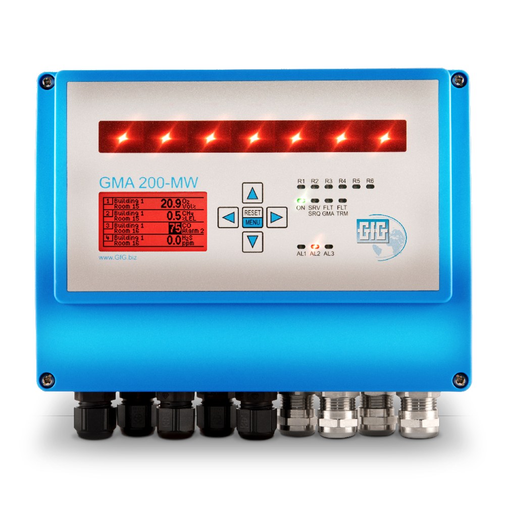
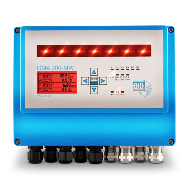
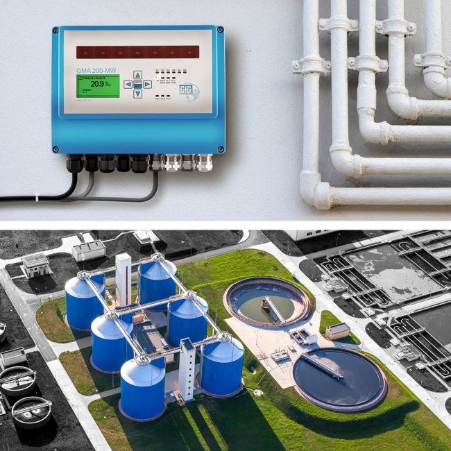
    The GMA200-MW4 is a wall-mounted controller for fixed gas detection systems monitoring toxic, flammable gases and oxygen concentration.

    In stock

    or
    Add to Quote

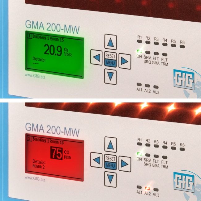
    The GMA200-MW4 is a reliable wall-mounted controller for complex fixed gas detection systems monitoring toxic and flammable gases as well as oxygen concentration. It supports up to 16 digital transmitters (4 of which can be analog) via RS-485 interface or 0.2-1 mA/4-20 mA lines. Features include 6 integrated relays (4 programmable), color-backlit 2.2″ display, 13 status LEDs, visual and audible alarm (100 dB), IP65 housing, and data logging via microSD card. Expandable to 68 relays using external relay modules. ATEX II (2) G certified, SIL 2/3 rated. Supply voltage: 100-230 V AC or 24 V DC.

    Description

    GMA200-MW4

    The GMA200-MW4 is a reliable wall-mounted controller for complex fixed gas detection systems monitoring toxic and flammable gases as well as oxygen concentration. It supports up to 16 digital transmitters (4 of which can be analog) via RS-485 interface or 0.2-1 mA/4-20 mA lines. Features include 6 integrated relays (4 programmable), color-backlit 2.2″ display, 13 status LEDs, visual and audible alarm (100 dB), IP65 housing, and data logging via microSD card. Expandable to 68 relays using external relay modules. ATEX II (2) G certified, SIL 2/3 rated. Supply voltage: 100-230 V AC or 24 V DC.

    Features

    • Monitors 1 to 16 measuring points

    • Suitable for every GfG transmitter

    • 6 integrated relays for safety measures, fault notifications and maintenance (4 of which can be programmed freely)

    • 0.2-1 mA, 4-20 mA or RS-485 (Modbus) connectivity

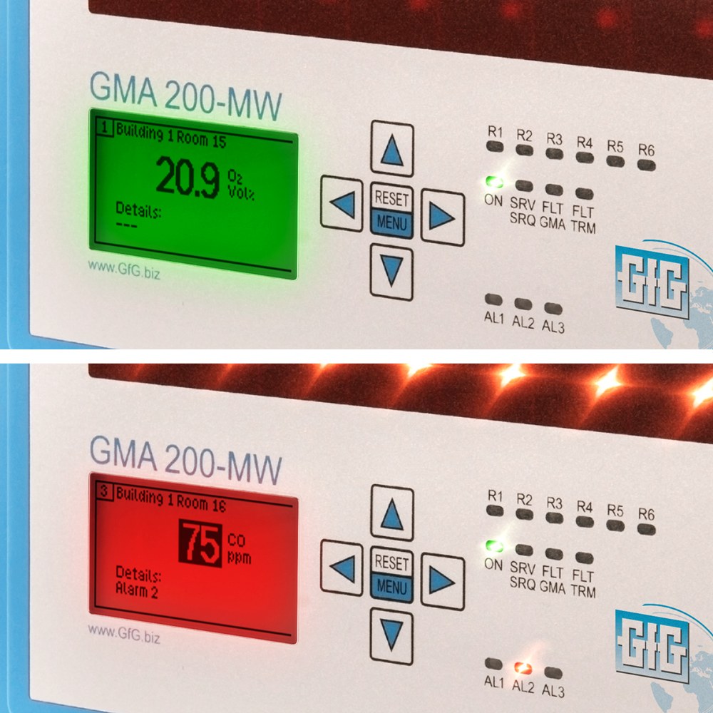
    • Color-backlit 2.2″ display

    • 13 colored status LEDs

    • Visual and audible alarm

    • Wall-mounted housing (IP65)

    • Data logger with microSD card option

    • Relay module expansion capability (up to 4 modules with 16 relays each)

    • Visualization software available (GMA200-VS)

    • Uninterruptible power supply option
    Specifications

    Status LEDs
    13 status LEDs for alarms, operating and relay states
    Display
    2.2 inch graphic display with 132 x 65 pixels
    Pushbuttons
    5 function keys
    Alarm
    Horn max. 100 dB(A) adjustable
    Operating voltage
    100-240 V AC 50-60 Hz mains voltage and/or 24 V DC (20-30 V DC) through stabilized SELV or PELV power supply unit
    Power consumption
    Max. 16 VA (without transmitters) Max. 42 VA (with transmitters)
    Fuses
    F1: T 500 mA changeable (for GMA200) F2: M 1 (for transmitters)
    Supply output Uout
    24 V DC ±3 % supplied by the internal power supply unit, otherwise 20-30 V DC (see above)
    Analog signal input IIN
    4x 150 mA or Iges=0.6 A with different allocation 4-20 mA or 0.2-1 mA Measuring tolerance: ±0.3 % MR @ 4-20 mA or ±1.2 % MR @ 0.2-1 mA (MR = measuring range) (Load approx. 50 to 100 Ω, Imax = 70 mA continuous / 500 mA short-time)
    Digital signals TRM bus 1+2
    RS-485; half-duplex; max. 38,400 baud
    Update time
    1s (If there are more than 16 transmitters and relay modules on the same TRM bus and the data transmission is only at 9600 baud, the cycle time is extended from 1.0 to max. 1.3 s, so that the time of 1 s cannot be maintained)
    Adjustment time for RS485
    Rise time t₅₀<2s or t₉₀<2sec Decay time t₅₀<2s or t₁₀<2sec
    for 4-20 mA
    Rise time t₅₀<2s or t₉₀<4sec Decay time t₅₀<2s or t₁₀<4sec
    for 0.2-1 mA
    Rise time t₅₀<6s or t₉₀<10sec Decay time t₅₀<6s or t₁₀<10sec (extended by setting times of the gas measuring transmitters)
    Ready delay
    <40s (can be extended by running-in times of gas measuring transmitters)
    GMA bus
    RS-485; half-duplex; max. 230,400 baud (for GMA200 relay modules, control center, PC, PLC or gateway)
    RS485 bus
    RS-485; half-duplex; max. 38,400 baud (only for GMA200 relay modules)
    Contacts
    6 relays with normally open contact
    Insulation distances
    Basic insulation between the relays: 1&2, 3&4, 5&6 Double insulation between the relays: 2&3, 4&5
    Contact load capacity
    3 A/250 V AC or 3A/30 V DC
    Minimum switching current
    10 mA
    Minimum switching voltage
    5 V
    Switching fequency
    Max. 100 per year (per relay contact), valid for SIL applications according to EN 50402
    IOUT1+2
    4-20 mA with linear transfer function (load max. 560Ω)
    Accuracy
    ±0.3 % MR @ 10 to 30 °C or ±0.8 % MR @ -20 to 50 °C (MR=measurement/signal range)
    Reset 1+2
    0-3V DC (alarm acknowledgement occurs on contact with GND; UMAX=30V DC)
    Mounting location
    Indoors only up to an altitude of 2,000 m above sea level
    Temperature for storage
    -13 to +140 °F / -25 to +60 °C | 0 to 99% r.h (recommended +32 to +86 °F / 0 to +30 °C | 40 to 60% r.h.)
    Temperature for operation
    -4 to +131 °F / -20 to +55 °C | 0 to 99% r.h.
    Protection class
    IP65
    Dimensions
    8.23 x 7 x 2.52 in / 209 x 180 x 64 mm (W x H x D)
    ATEX approval
    ATEX 94/9/EC
    Electromagnetic compatibility
    EN 50270:2015 (Interference emission: Type class I, Interference immunity: Type class II)
    Electrical Safety
    EN 61010-1:2010 (pollution degree 2, overvoltage category III for relay contacts)
    Functional Safety
    EN 50402:2017; IEC 61508-1 to -7:2010 (SIL2/SC3)
    Metrological suitability
    EN 50271:2018; EN 62061:2016; ISO 13849-1:2015 EN 60079-29-1:2016 (EX); EN 50104:2010 (OX); EN 45544-1/-2/-3:2015 (TOX)

    CONTACT US